

MOSFET Selection in a BMS: Four Criteria and Three Pitfalls to Avoid
A MOSFET in a BMS is the switch that executes safety actions, not an optional protection component. The core criterion is calculating on-resistance at operating junction temperatur
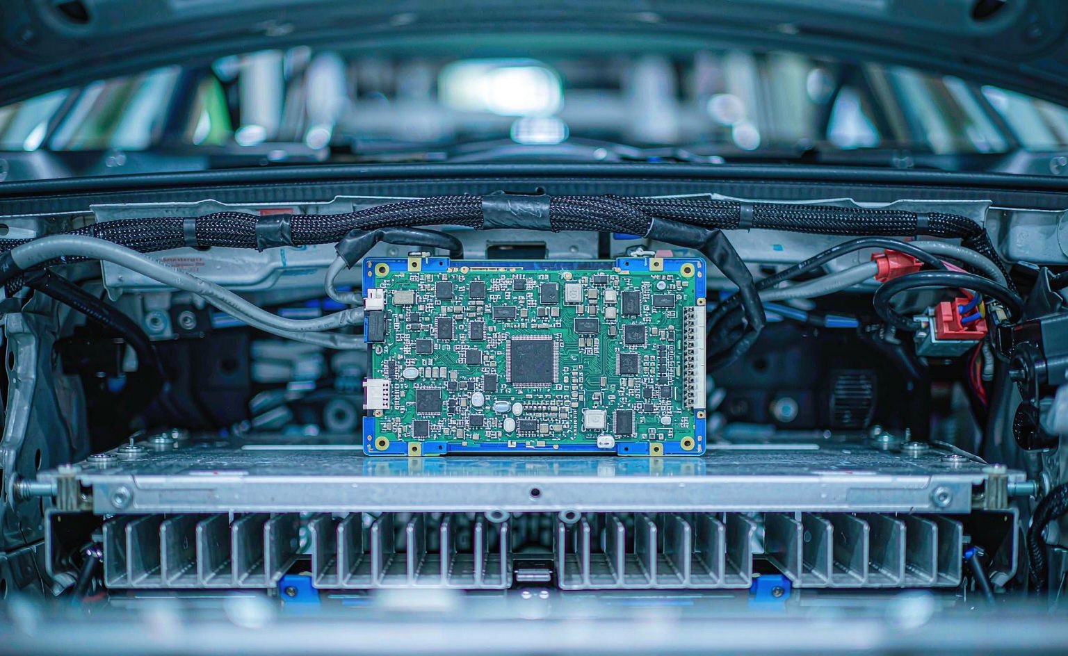
A MOSFET in a BMS is the switch that executes safety actions, not an optional protection component. The core criterion is calculating on-resistance at operating junction temperature, and the series resistance of back-to-back devices plus body-diode loss are the two most commonly underestimated factors.
Bottom Line First: What Logic Should Drive MOSFET Selection in a BMS?
If your BMS design meets the conditions below, selection should treat "on-resistance × temperature drift" as the primary criterion:
- Charge/discharge current above 5A — conduction loss starts to become the dominant efficiency drag
- The pack uses natural convection cooling — the cells tolerate no additional heat source, so MOSFET dissipation is pure burden
- Bidirectional cutoff is required — both charge and discharge paths must be interruptible, typically requiring a back-to-back dual-device arrangement
Conversely, for low-current protection only (below 1A), system cost and leakage current matter more than on-resistance — no need to chase ultra-low RDS(on).
Four Critical Roles of MOSFETs in a BMS
In a battery management system, MOSFETs are not an "optional protection component" but the switch that executes core safety actions. They serve four main functions:
1. Charge/Discharge Control
Through precise gate voltage control, MOSFETs switch rapidly to regulate current flow in the charge and discharge paths. They limit charge current and prevent overcharge during charging, and prevent over-discharge during discharging. This is the BMS's most fundamental and most frequent operation.
2. Battery Protection
Battery packs suffer damage under abnormal conditions such as overcurrent, overvoltage, and overtemperature. The MOSFET's fast response allows it to detect and disconnect the battery in real time. Working with sensors and protection circuitry, it responds immediately when a danger signal appears — for example, cutting the charge/discharge loop when temperature rises too high, preventing thermal runaway.
3. Temperature Management
MOSFETs work alongside temperature sensors in pack thermal management. When temperature exceeds a preset range, they rapidly interrupt current between the battery and the load, preventing damage from overheating.
4. Balancing Control
In multi-cell packs, capacity and internal-resistance differences cause cell voltages to diverge over time, degrading overall performance. MOSFETs work with the balancing circuit to equalize cell voltages, preserving overall efficiency and service life.
Four Core Selection Criteria
Criterion 1: Voltage and Current Ratings — Cover the Full Operating Range
Choosing a MOSFET with appropriate voltage and current ratings is the precondition for system reliability. The blocking class should exceed the pack's maximum voltage with margin for switching spikes, while current capability must cover full-load charge/discharge current plus transients.
Criterion 2: On-Resistance — But Calculated at Operating Junction Temperature
On-resistance RDS(on) directly determines conduction loss. Lower on-resistance means lower dissipation, less heat, and higher system efficiency.
Key caveat: MOSFET on-resistance has a positive temperature coefficient. From 25℃ to 125℃ junction temperature, RDS(on) typically rises more than 50%. Selection must look up the actual value at the expected maximum junction temperature rather than using the room-temperature nominal figure.
Criterion 3: Switching Speed — Determines Whether Protection Acts in Time
Switching speed is another parameter deserving close attention. For efficient charge/discharge control, a MOSFET should offer low on-resistance and fast switching response, reducing dissipation and improving system efficiency. In overcurrent protection, switching speed directly determines whether the protection window is adequate.
Criterion 4: Thermal Performance — The Critical Item in Naturally Cooled Systems
In high-power applications, MOSFET dissipation and heat generation affect both performance and lifespan. Thermal management must be designed properly to keep the MOSFET within a safe temperature range. In naturally cooled systems where cells tolerate no additional heat source, device thermal resistance and package thermal design tend to be constraints rather than optimization targets.
Key Parameters at a Glance
| Criterion | Parameter | Selection Point |
|---|---|---|
| Blocking voltage | VDS | Above pack maximum voltage, with switching-spike margin |
| Current | ID / IDM | Cover full-load current and transients |
| Conduction loss | RDS(on) | Verified at maximum junction temperature, not room temperature |
| Switching speed | td(on) / tf | Affects the protection response window |
| Drive loss | Qg | Low gate charge simplifies the drive circuit |
| Thermal performance | Rth(j-c) | A constraint in naturally cooled systems |
| Maximum junction temperature | Tj,max | Sets the safe temperature ceiling |
Typical Application Scenarios
- EV traction battery packs — high voltage (400V/800V platforms), high current, requiring multiple paralleled devices
- Energy storage systems (ESS) — long-duration continuous charge/discharge with heavy thermal demands
- Portable power stations — compact form factor, predominantly natural convection
- Power-tool battery packs — high pulsed current output with pronounced transient thermal stress
Three Common Selection Pitfalls
1. Calculating Loss from Room-Temperature RDS(on)
This is the most common and most damaging error. MOSFET RDS(on) rises significantly with temperature. Calculating loss from the room-temperature nominal value underestimates actual heat generation by more than 50%. The correct method: estimate junction temperature → look up RDS(on) at that temperature → calculate loss → recalculate junction temperature, iterating to convergence.
2. Ignoring the Series On-Resistance of Back-to-Back Devices
Bidirectional cutoff requires two MOSFETs in back-to-back connection, so the total on-resistance in the loop is the sum of both devices (including contributions from the body diodes). If selection is based on a single-device figure, actual loss will be double the estimate.
3. Underestimating the Body Diode During Freewheeling
In inductive-load applications such as motor drives, the body diode carries the freewheeling path. Body-diode forward voltage and reverse recovery behavior affect system efficiency. This loss is often inconspicuous in datasheets but accounts for a meaningful share in actual operation.
Frequently Asked Questions
How are NMOS and PMOS divided in a BMS?
The basic division: NMOS for low-side switching, PMOS for high-side switching. A low-side NMOS is relatively simple to drive (source near ground potential) but breaks the connection between load and ground. A high-side NMOS requires a bootstrap circuit or charge pump, whereas a PMOS can be controlled directly by gate voltage. The specific choice depends on your circuit topology and protection logic requirements.
Why do BMS designs often place two back-to-back MOSFETs in the charge/discharge path?
Because of the unidirectional conduction of the body diode. After a single MOSFET turns off, its body diode still provides a reverse conduction path, so current cannot truly be interrupted. With two devices in back-to-back configuration, one body diode is always reverse-biased regardless of current direction, achieving genuine bidirectional cutoff. This is also the circuit foundation for independent charge and discharge control (separate charge and discharge FETs).
How do I know whether selection leaves enough margin?
Check three dimensions. Voltage — blocking class should exceed the pack's maximum voltage by at least 1.2×. Current — continuous rating should cover peak operating current, and pulsed rating should cover short-circuit transients. Thermal — at maximum ambient temperature under worst-case conditions, steady-state junction temperature should be at least 25℃ below Tj,max. Only when all three are satisfied is the margin adequate.
Summary
The role of MOSFETs in a BMS is that of the switching device that executes safety actions. Selection is not about maximizing any single parameter but about finding the balance point among blocking voltage, current, on-resistance, switching speed, and thermal performance that matches the specific pack's operating conditions. Of these, "calculate on-resistance at operating junction temperature" is the most easily overlooked and the most likely to cause design rework.
Need a BMS power-device selection study for a specific pack? Tell us your pack voltage, charge/discharge current, and cooling method, and we will recommend a matching device combination.